Electric Current and Circuit
Electric Current and Circuit
We know various components are needed to build an electrical circuit. To understand the electrical circuit and the flow of current, one must understand the electrical symbols of circuit components. In this article, let us discuss in brief about electric circuit and its components.
Electric Circuit
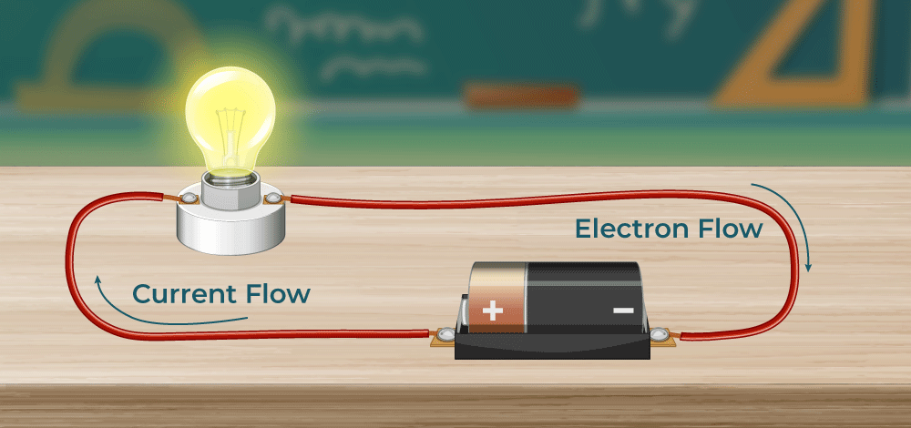
The electric circuits are closed-loop or paths, forming a network of electrical components where electrons can flow. This path is made using electrical wires and is powered by a source, like a battery. The start of the point from where the electrons start flowing is called the source, whereas the point where electrons leave the electrical circuit is called the return. Let’s conduct a small experiment; you would need the following,
Electric bulb
Wire
Electrical tape
A battery
Connect the wires to the bulb and connect one end of the wire to the battery. Notice what happens, there won’t be any change in the bulb, but when you connect the free wire to the battery and complete the circuit, you will notice that the bulb starts glowing. Therefore the circuit must be completed for the current to flow. An electrical circuit is complete only when there is at least one closed loop from the positive to the negative end. This is the simplest form of an electric circuit. The circuit found inside a television is more complicated and has different components. You might have seen these danger signs on electric poles, transformers, and sometimes even on some electrical equipment at home. It is to warn you about the dangers of electricity, and electricity, if not handled properly, could be lethal and can even cause death. Electric wires sockets and live wire should be adequately insulated and kept away from the reach of children, the voltage in a small battery does not exceed more than 12 volts, but the voltage in a transformer may reach up to 11000 volts. Faulty electrical circuits because fire, for fires caused due to electrical failure use of water to extinguish must be avoided, there are special extinguishers for the same. We have come to a conclusion that electric current flows only when there is a complete uninterrupted connection from a battery through different components back to the battery. Any interruption will stop the flow of current Electric batteries should also be handled carefully; never connect two terminals of the battery without a bulb or a load because the chemicals inside the battery react so quickly that they generate an immense amount of energy, which can even cause them to burst.
Electric Circuit Symbols
Every component and product of the electric circuit contains a symbol. The symbols represent parts of the circuit in a circuit diagram. Beneath are the basic set of symbols that are present in a circuit diagram.
Simple Circuit
A simple circuit comprises the power source, conductors, switch, and load.
Cell: It is the power source. Load: It is also termed as the resistor. It is a light bulb that lights when the circuit is turned on. Conductors: They are made of copper wires with no insulation. One end of the wire is connected to the load to the power source, and the other end of the wire connects the power source back to the load. Switch: It is a small gap in the circuit. There are various types of switches. A switch can be used to open or close a circuit.
Circuit Diagram
In this article, we will explore circuit diagrams in a comprehensive way, understanding their purpose and what they consist of. Examples of circuit diagrams that showcase different circuit configurations and the symbols used in them are explained. We will also take a closer look at the components we often come across in circuit diagrams, such as resistors, capacitors, and switches, and explain how they are represented with symbols. By the end of this article, you’ll have a solid understanding of circuit diagrams and how they represent electrical circuits.
What is a Circuit Diagram?
A circuit diagram, also known as an electrical diagram, elementary diagram, or electronic schematic, is a graphical representation that simplifies an electrical circuit. It serves as a visual tool for the design, construction, and maintenance of electrical and electronic equipment. By utilising either images of distinct components or standard symbols, a circuit diagram presents a simplified depiction of the circuit’s elements and their interconnections. This enables electricians and technicians to easily understand the relative positions of the components and their relationships within the circuit. Reading a Circuit Diagram To illustrate the concept of circuit diagram, refer to the following figure showcasing a simple circuit diagram. The given circuit diagram consists of components such as a voltage source, a voltmeter, an ampere, and a resistor. In the next few sections, we will explore how to identify and interpret symbols for voltage sources, resistors, capacitors, inductors, switches, and more. By understanding these symbols and their meanings, we can understand how different elements in a circuit are connected and how they function together.
Ohm's Law
Ohm’s law states the relationship between electric current and potential difference. The current that flows through most conductors is directly proportional to the voltage applied to it. Georg Simon Ohm, a German physicist was the first to verify Ohm’s law experimentally. One of the most basic and important laws of electric circuits is Ohm’s law.
Ohm’s law states that the voltage across a conductor is directly proportional to the current flowing through it, provided all physical conditions and temperatures remain constant.
Mathematically, this current-voltage relationship is written as,
In the equation, the constant of proportionality, R, is called Resistance and has units of ohms, with the symbol Ω. The same formula can be rewritten in order to calculate the current and resistance respectively as follows:
Ohm’s law only holds true if the provided temperature and the other physical factors remain constant. In certain components, increasing the current raises the temperature. An example of this is the filament of a light bulb, in which the temperature rises as the current is increased. In this case, Ohm’s law cannot be applied. The lightbulb filament violates Ohm’s Law.
Ohm’s Law Statement: Ohm’s law states that the voltage across a conductor is directly proportional to the current flowing through it, provided all physical conditions and temperature, remain constant. Ohm’s Law Equation: V = IR, where V is the voltage across the conductor, I is the current flowing through the conductor and R is the resistance provided by the conductor to the flow of current.
Analyzing rows 1, 2 and 3, we come to understand that doubling and tripling the voltage leads to doubling and a tripling of the current in the circuit. Likewise, when we compare rows 1 and 4 and rows 2 and 5, we come to understand that doubling the total resistance serves to halve the current in the circuit.